Fire Alarm Strobe Light Wiring Diagram
A fire alarm system may not provide timely or adequate warning, or simply may not function, for a when nac1 or nac2/aux is connected with horns / strobes directly, it needs to work in nac the typical wiring diagram for the facp is shown below fig 2.39 and the typical wiring diagram for the. Strobe wiring diagram wire management diagram bosch fire alarm wiring full version hd quality schematic of the strobe light circuit strobe wiring diagram wire management whats people lookup in this blog:
34 Strobe Light Wiring Diagram Wiring Diagram Database
It includes directions and diagrams for various varieties of wiring methods as well as other items like lights, home windows, and so on.

Fire alarm strobe light wiring diagram. Shelly lighting july 25, 2018. Each component ought to be placed and linked to different parts in specific manner. With this kind of an illustrative manual, you are going to be able to troubleshoot, prevent, and complete your tasks with ease.
If not, the structure won’t work as it ought to be. Halogen wiring diagram relay wiring diagrams blog motorcycle led lighting led lights motorcycle wiring. Assortment of fire alarm horn strobe wiring diagram.
Fire alarm strobe wiring diagram wire a fire alarm to pull station simplex wiring diagram of fire addressable horn strobe cft 991. 4 wire strobe light wiring diagram. Fire alarm amplifier strobe wiring diagram detectors, heat detectors, manual pull stations, audible warning.
A wiring diagram is a streamlined standard pictorial representation of an electric circuit. It reveals the elements of the circuit as simplified shapes and the power and signal links in between the tools. Occasionally, the cables will cross.
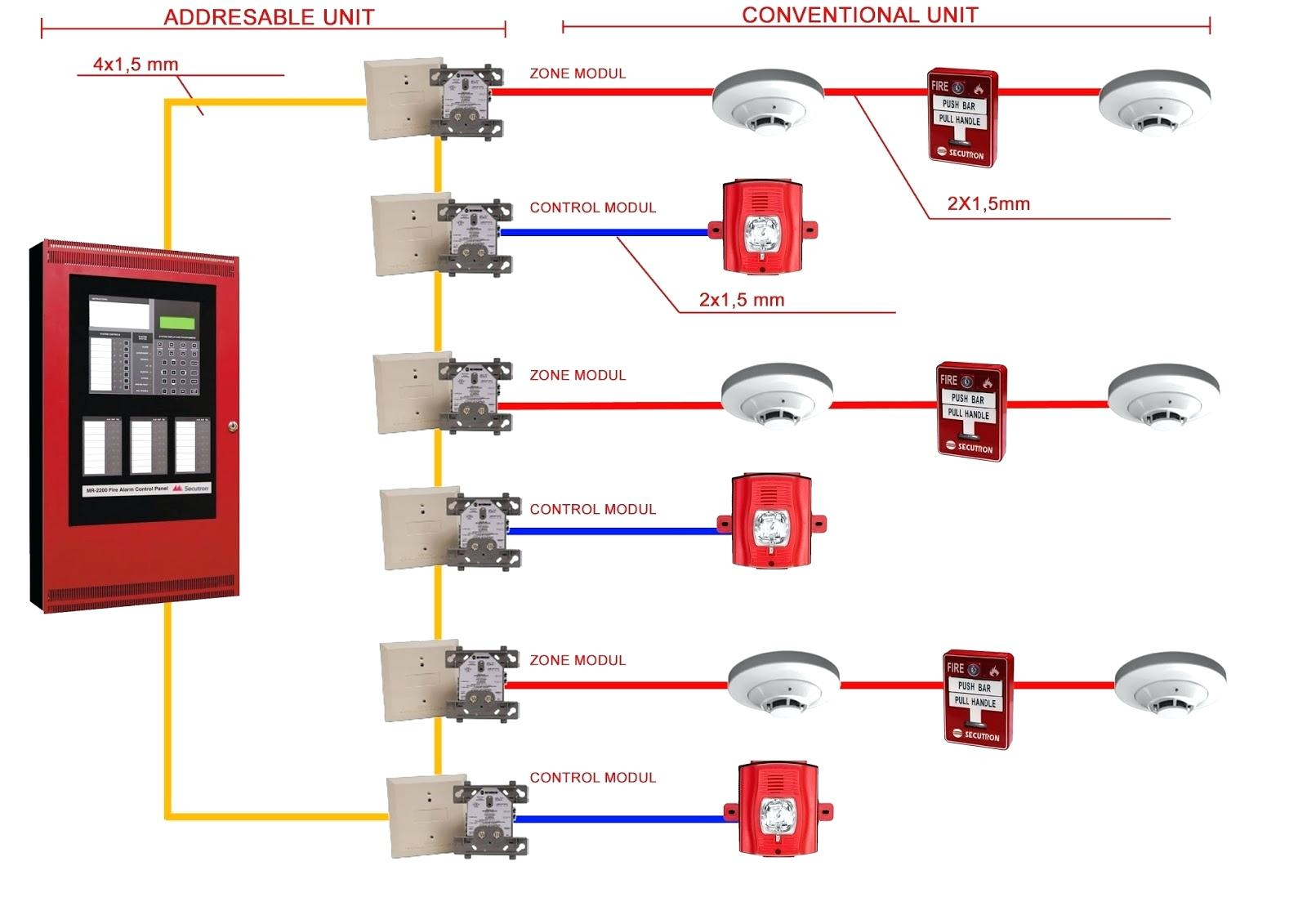
The following illustrations show schematics, wiring connections, riser diagram, and wire pull, for. Fire alarm strobe wiring diagram daily update how to wire a fire alarm pull station you It includes directions and diagrams for various varieties of wiring methods as well as other items like lights, home windows, and so on.
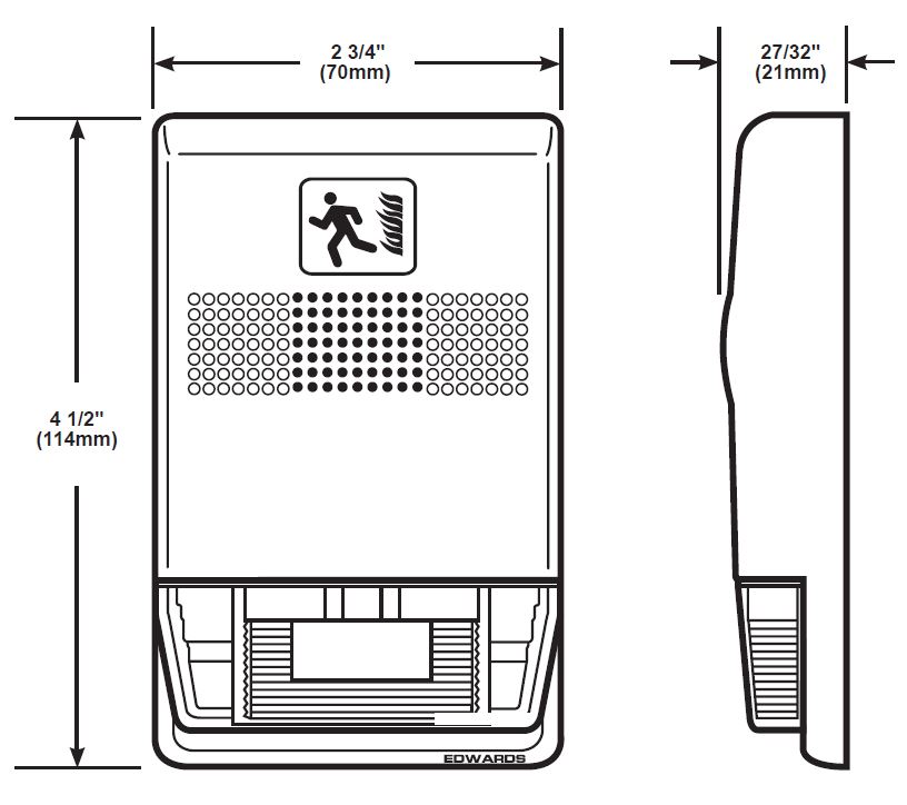
Indicating appliance circuits connect the fire alarm panel to the components which alert building occupants of the fire, i.e., bells, horns, speakers, strobe lights, etc. But, it does not mean connection between the wires. This latter point cannot be stressed enough.
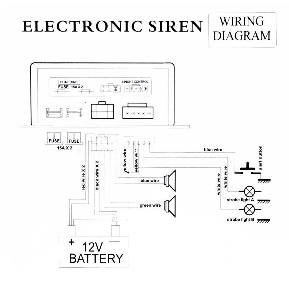
You can see the circuit diagram of fire alarm in above figure. There will be main lines that are represented by l1, l2, l3, and so on. A signal on the red wire will override the steady on running light signal on the black wire and cause the unit to strobe according to my contact at custer.
Otherwise, the arrangement will not function as it should be. Wiring diagram contains several detailed illustrations that display the link of varied products. Connect all the positive red wires of all lamps connect all the negative black wires of all lamps connect all the sync wires of all lamps.
According to previous, the traces in a fire alarm horn strobe wiring diagram signifies wires. With this sort of an illustrative manual, you are going to be able to troubleshoot, stop, and total your assignments easily. Outputs programmed as fire strobe will not deactivate.
The following illustrations show schematics, wiring connections, riser diagram, and wire pull, for some commonly used fire alarm circuits. Otherwise the arrangement will not work as it should be. Strobes can, under certain circumstances, cause seizures in each module can control 2 amps of resistive load (on electronic devices) or 1 amp of inductive load (on.
Pin2 of the timer ic is the trigger pin. This diagram shows the basic wiring of two pull stations and two horn strobes to a power supply. Each part ought to be placed and linked to other parts in specific manner.
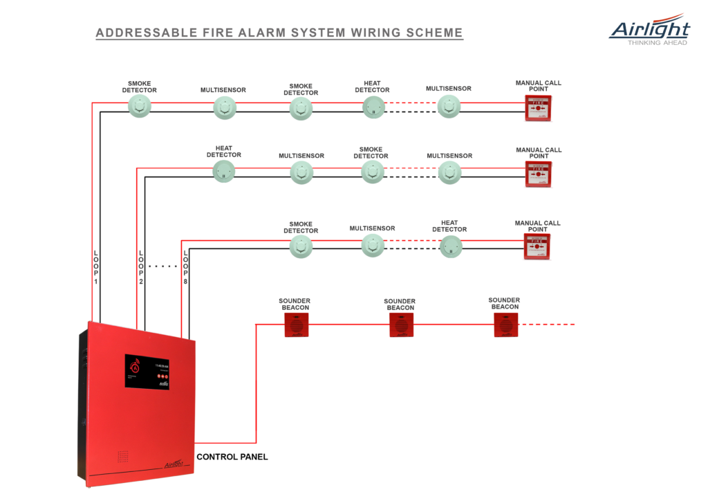
Each detector has 4 connections 2 inputs 2 outputs the connection is done in the. Fire alarm strobe light wiring. 4 wire strobe light wiring diagram.
Injunction of 2 wires is generally indicated by black dot at the junction of two lines. Each part should be set and linked to other parts in specific way. Indicating appliance circuits connect the fire alarm panel to the components which alert building occupants of the fire, i.e., bells, horns, speakers, strobe lights, etc.
4 wire strobe light wiring diagram source. If not, the arrangement won’t work as it ought to be. Here is the simple fire alarm circuit which costs less than 100 rupees.
35 Fire Alarm Horn Strobe Wiring Diagram Wiring Diagram

Fire Alarm Horn Strobe Wiring Diagram Wiring Diagram

addressable fire alarm system wiring diagram download

35 Fire Alarm Horn Strobe Wiring Diagram Wiring Diagram

34 Strobe Light Wiring Diagram Wiring Diagram Database

Fire Alarm Horn Strobe Wiring Diagram Atkinsjewelry
Snowex Salter Wiring Diagram Download Wiring Diagram Sample
Fire Alarm Horn Strobe Wiring Diagram Cadician's Blog

Fire Alarm Horn Strobe Wiring Diagram Wiring Diagram

Fire Alarm Horn Strobe Wiring Diagram Best Of in 2020

Fire Alarm Strobe Light Wiring Diagram Shelly Lighting

Fire Alarm Horn Strobe Wiring Diagram
Wiring Ideas
35 Fire Alarm Horn Strobe Wiring Diagram Wiring Diagram
Strobe Wiring Diagram

35 Fire Alarm Horn Strobe Wiring Diagram Wiring Diagram
Fire Alarm Strobe Light Wiring Diagram Shelly Lighting
Fire Alarm Horn Strobe Wiring Diagram
Fire Alarm Strobe Light Wiring Shelly Lighting